Beschreibung
Wichtige Erkenntnisse
- Learn how to add stiffeners, holes, and connection in beams using Advance Steel
- Learn how to prepare fabrication documents
- Learn how to use MWF (By StrucSoft Solutions) for stud wall detailing
- Learn how to prepare erection drawings
Referenten
- TPTony PoulinIn the structural steel industry for 30 years, I graduated from school in 1987 as an Architectural Technician. I started detailing steel by hand and Autocad in a medium sized structural steel fabrication firm. In 1990, I helped a new structural steel fabrication company start from scratch. In 1993, I moved to Canam Group as a steel detailer, before becoming chief Draftsman for Steel Plus Network, a Canam Group division which was groupings of structural steel fabricators in North America. I taught structural steel detailing in college for two years. I was the Quebec Chapter Director of the NISD from 1999 to 2002. I contributed to the second and third edition of the book Detailing for Steel Construction published by the AISC in coordination with the NISD. I am now a Drafting Manager at Canam Group for a team of 75 draftsmen using 3D softwares including Revit and Advance Steel. Canam Group has 23 shops in North America, offices in Romania and India and employs 4650 people.
- CLCarolann LachanceI graduated from school in 2015 as an Architectural Technician.I started my career at Canam Group as a Revit drafter, doing layout drawings for commercial, institutional and light industrial buildings. I learned Advance Steel 1 year ago and now use both sortwares to produce layout and shop drawings for buildings with prefabricated light gage stud walls.
TONY POULIN: We'll talk about using Revit and Advance Steel for heavy and light-gauge steel detailing. So I'm Tony Poulin, from Canam Group, Drafting Service Manager. And my co-speaker is Carolann Lachance, Drafter at Canam.
This is my background. I'm in the structural steel industry for 30 years. And then I graduated in '87, as an Architectural Technician. And I now a Drafting Manager for Canam Group, managing a team of a 65 draftsmen using different 3D software, but including Revit and Advance Steel.
Carolann, she's been working at Canam for two years. She graduated as an Architectural Technician also. So Carolann and I have the same school degree, but almost 30 years apart. So where we are from, we are from Eastern Canada, from the province of Quebec.
It's a huge province. You know, the country of France fits three times in this province. And our largest shop and our head office are located in Eastern Canada.
Now I want to explain why Carolann and I have an accent. I guess you heard that. The Quebec province is the French-speaking province. It's full of French Canadian, about eight million French-speaking people. And there are very strict laws to protect French.
Even well-known banners adapt to the French. They change it on their sign, the name. It's a loss. Some can keep their name, but it's better if they change it in French.
We'll have about 5, 10 minutes at the end for questions. We'll keep the questions for the end, please. This is the summary of the class. I'd like to remind you that we are in the early stage of implementing Advance Steel and StrucSoft add-ins. So this class is for beginners.
So you will learn, after this class, how to add stiffeners, holes, connection in beams using Advance Steel; how to prepare fabrication documents; how to use the MWF-- by StrucSoft Solution-- for stud wall detailing. MWF stands for Metal Wood Framing; and how to prepare erection drawings. So this is the agenda. So the first part will be this PowerPoint part. And the second part will be a live demo by Carolann.
A company overview. So Canam Group is the largest manufacturer of steel component in North America. We do a 10,000 project per year, with an annual production capacity of more than 800,000 tons. We have more than 4,600 employees, 23 plants in North America. Six teams are in the US. And we have offices in Romania and India.
We do buildings, structural steel, bridges. And the markets we target are everything that have structural steel in it. So the product we have, mainly we are joists and deck manufacturer. But we also have other product, like the Hambro composite floor system. Basically it's a composite joists system.
We have a load-bearing steel stud wall. And this is the main topic of this class. We also have a Murox building system, which this is wall panels made of structural steel. But it includes the exterior, interior finish, the insulation, the membrane, the doors, windows.
We also have a Econox prefabricated building, which is similar to a Murox building. But the roof is also made with prefabricated panels instead of a standard joists and deck roof. We do structural steel and also engineered wood.
We started using Revit in 2008, with five licenses. After two years, 50% of our layouts and general drawings were done using Revit. And after three years, 80%.
Today we have a 95% of our layout done with Revit. The other 5% are these Econox buildings, which are done with AutoCAD. We have 27 license in Canada and USA, 11 in Romania, and 14 in India.
In the next slide I will often say our RMR. RMR stand for Residential and Multi-Residential project. Because this is mainly in these kind of buildings that we use Advance Steel and MWF.
Few years ago, Canam decided to go in the RMR market, the Multi-Residential market. At that time we offered structural steel, Miscellaneous steel, and our joist composite system. But we also added precast balconies and prefabricated load bearing stud walls.
The job here on the picture is a job we did four years ago. It's Creve Coeur, Missouri. And four years ago, we didn't have the capabilities of detailing walls or fabricating walls. So everything was subbed out.
Targeting a new market meant having new challenges. The challenges we have with these multi-residential buildings, one of them is there are multiple grid lines. Nothing is aligned. because the steel are in the walls. And the walls are not aligned. So even the underground parking garage concrete columns are not aligned with the upper steel columns.
And the steel, that steel must fit in the walls. The columns are small. There's a lot of offset connections, so it's a challenge to connect the structural steel, or the beams and the columns together in a very tight spot. Another challenge we have on this kind of project is since there are multiple grid lines, the concrete guys are struggling with the anchor bolt placement. So the accuracy is not as sharp as on industrial or commercial buildings.
What we do is we have a site survey done just before delivery of our walls and steel on site. And we adapt the base plate of the column to suit the site condition. Here on this example, you see we did an expansion of this building.
And we had a site survey. But the site survey was done with a 3D scan. This is a scan of the project. And here on the next slide, we can see the real project And sometimes we superimposed the 3D scan with the Revit model, so we can see if there are discrepancies between the site condition and our model.
Another challenge we have, these buildings are located in residential areas. So there's not a lot of room to store the steel on site. Here it might seems that there is a lot of room.
But this building was in Edmonton, Alberta, in Western Canada. And the city didn't allow us to store any steel outside of this concrete fence. Because of that, we need to deliver the right material at the right time. It's a challenge, there is no room on site to store the steel. And on this particular building, it was so tight that we ended up installing the tower crane in the elevator shaft.
Other challenges we have is we need to figure out the ductworks, the pipeworks, and also the connection of the balconies. Because we need to provide a connection here that take into account the thermal bridge between the steel outside and the steel inside. And like I told you, there's not a lot of room to connect our pieces together. So it's a challenge.
Now the implementation of our new software. Because we had these new product to detail, we needed new software. And when we were looking for new software, we also had to figure that with these multi-residential building, we have a lot more collaboration to do with the architects.
We wanted the software that were Revit compatible. And this new software needed to have the capability of transferring data to our shop and to our purchasing department. And also, the shop needed a 2D drawing for assembly. And the erectors needed a 2D drawing to erect the steel on site.
For the stud wall detailing, we chose MWF by StrucSoft Solutions. We train three draftsmen and we started on the real project one week after the training. And it wasn't a small one. It was a 10,000 linear feet of stud wall project. It was a large one. We had just 12 weeks to detail this project. Now we have five MWF user at Canam.
These stud walls are made of a light-gauge stud. But at the top we have a transfer beam. And this beam is a structural steel beam, a wide-flange beam. We needed a software to detail these beams. We chose Advance Steel, which is an Autodesk software. It met our requirements of having some software Revit compatible.
We bought four licenses and train the draftsmen. So we prepared the shop drawing templates. We tested the sub-material and the purchasing list with our different department to make sure it work.
We tested, also, the CNC and the DXF. We had training in Saint-Georges, Quebec, and also in Romania. Because we have two licenses in Quebec, and two licenses in Romania.
This is our workflow. Right after the design we start a model, sticking the project in Revit. In parallel, our connection engineers do the sketch. So we complete the drawing of the stud walls in Revit with the MWF add-in. And when it's done, when everything is checked, we start using Advanced Steel to detail our header beam.
We make sure the stud walls are checked, because it's easier to start detailing the beam. Because we know where the wall ends, where it starts. This is set at this stage, when we detail the light-gauge wall. We are sure it match, the steel will match the wall when we do like that.
We do the shop drawing. We prepare the 2D drawings. We check them. And at the end, we issue a package either for shop, or for approval, depending if an approval is required. At the end, we prepare the erection drawings. This process take between 4 to 16 weeks. But sometimes it can take years.
From the Revit model, we Export it to Advance Steel, using the Advanced Steel add-in for Revit. So we export the beams, but we also export the posts. The posts are made of light-gauge, but we export them. For reference, Carolann will explain you why we do that.
What do we do in the model here, for the wall, we do the 3D modeling of the corner joint, the post, the wall component. And with Advance Steel, we modelize the beams, the connection. The lifting holds, stiffeners, and then some studs.
We also need it to suit job site needs and our shop needs. The shop needs was they wanted to have the shop drawings similar to what they used to work with before. They wanted a list of material. They wanted CNC, DXF, and a field bolt list.
Here, on the picture here, you can see in the yellow rack there are some header beams ready to be installed on the light-gauge stud wall in our shop. So this is the material list we provide to the shop. So it has to include every material that is required for the fabrication of the wall, including every single screws.
Now I'll show you, with this short video, how to create a CNC and DXF. First we will zoom in. And we'll launch a query of Division 23, Execute. That beam turn red. So we go into the Advance Steel Tool Palette, select the beams. They turn blue.
Now in Output, NC Settings. We will add a 1 to the NC Extension to have an NC1 extension. We go in the NC comment. So the calculation is done. NC file have been created.
In the Document Manager, we can see in the DSDV file that the NC1 of this division, 23, have been created. And to the right there is a preview window where we can see the NC data. We'll close everything. And we'll create the DXF.
We go in the NC Settings. Again, we erase NC1, We don't need to write DXF, because by default it's a DXF. We choose DXF for plates, because we don't want DXF for other material than plates.
This is the calculation process. NC file has been created. Let's go to see in the Document Manager and the DSDV folder. So the DXF are there. And to the right there is the Preview window, where they give us an idea of what the plates look like. And those are the DXFs of Division 23. Because this is the division we selected.
Now, another short video. I'll show you how we create a Field Bolt List. So we launch a query. We'll still execute Division 23 with the Advance Steel Tool Palette. We select the beam and they turn blue.
In the Bill of Material, here we will substitute the flag for the head icon, because we want to use our templates, the templates we created. Now, the calculation process. Here is the field bolt list of the Division 23. And it's possible to save the list in an Excel format.
We'll go see in the Document Manager. We'll close everything. In the list, we can see that the field bolt list is there. And there are still, always, to the right, the Preview window, where we can have an idea of the bolt list.
Now, the job site needs. We needed to provide the site and erection drawings. They wanted to have the clear location of walls.
Because the accuracy of the location of these wall is very important. They wanted to receive the material just in time, for the reason I told you before. And you also needed a safety fence installation.
We also needed to provide a loading list. Because always for the same reason, to deliver the right material on the right time. But also to maximize the load. Because our shop is located in Eastern Canada, so when we ship these walls in Western Canada, or somewhere in the US, transportation can become very expensive. So we have to maximize the loads.
Here I'll show you how we create an erection drawing and the cut list. So we'll select a wall. It's the same wall that Carolann will use in her live demo.
Let's see this wall on the Plan view. We can see it's blue. It's not created yet. The last one we created is W 312.
We'll go to see the cut list of this division, which is Division 33. If we go down and look at the last beam created, it's W 312. Now we'll create the wall W 330.
We go in the MWF add-in and choose Quick Create. It will generate the wall. We'll see the stud appear.
There was some warning message, but they are not so important for now. We will rename this panel W 330. We can see the mark appear in the model.
Here we are assigning a piece mark for every sub material that is in the wall. And here we select our template to get the shop drawing on our template, standard template. So now this is the calculation process. There is a lot of data to process.
You'll see a few warning messages. But it's just some notice. It's not so important. Just read them and it's OK. So nothing wrong here.
We'll go to see the shop drawing of the wall. This is the shop drawing. We can see the piece mark, W 313. We can see the Material List, which includes all the sub material, including the header beam. And the Elevation view for the assembly in the shop.
So we see on the Plan view, the W 13 has been created. We can see the vertical studs. And we'll go back in the cut list. We can see that the W 13 has been created, and it includes all the material and the right length.
Some pictures of our finished product. OK, here you can see that in our shop we installed the Sheetrock on the perimeter wall. You can see here, this is an interior wall. So we don't install the sheet rock for interior walls. So we have to brace them for transportation and erection.
Here this is our composite joist system, with the TOPCOR embedded in the concrete slab. Here we can see a post made of several studs attached together. Here you can see header beams connections.
From the model, we extract the erection drawing, the shop drawing of the wall, the cut list, the buying list, the shop drawing of the header beam. Here you can see that when there is not much load in the header beams we connect them together with just one bolt. It's just for erection only.
There is always a small amount of actual load to pass through the beams. But we pass them through the Rebar in the concrete slab. So in Carolann's demo you will see this type of connection. It's time for the live demo. Carolann?
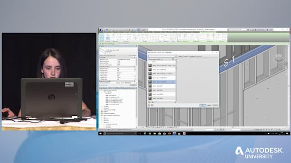
CAROLANN LACHANCE: OK, so just to get you in context, this is how we we'll proceed for this slide demonstration. At first we are going to start it in Revit, and MWF add-in for bundling these wall panels, including the header beams. We will also detail a panel with StrucSoft MWF, which is a detailing software for light-gauge material.
Then we will import the header beams created with MWF from Revit to Advance Steel, which is a detailing software for structural steel. Finally, we will use this software to produce these different document for shop and detailing the header beam itself.
Now, the model that you see on the screen is actually the first project that we've made with these three software combined. Its name is White Pine. We detailed last winter just after our training on Advance Steel. We are going to use it as a background for this live demonstration.
If we look to our demo there, we can see that it already contains two types of wall. The first one are those that we have on the ground floor and on the second floor. So if I zoom in a little bit, we can see that it already contains every component that we need to build a complete stud panel, which is the studs, the bridging right here. We have the bottom track and the top track and the header beams. Basically those wall are completed.
If we look at the third floor, the third-- excuse me, the third floor and the fourth floor, we have some generic walls already splitted in the front panels. And they contain their windows that came from Revit. At this point, everything has been made with Revit only. And what we are going to do for this live demonstration is that we are going to use MWF for adding some parameters in these empty walls. And then we will generate the studs in it and all the component.
For the needs of the presentation, I will focus only on these two panel here in the corner. Notice that I have already displayed this panel above. Because I'm going to use the posting in it to show you a little trick on the Advance Steel platform. But I'll be back on it later. For now, just focus on these two panels.
The first parameter that I'm going to add is a corner rule. This rule will tell which are assembly stud will be used to build a corner between my two panels. Basically there are two simple steps to create that this rule.
The first one is creating a folder that will contain the rule itself. For it I have to go in the to StrucSoft Solution tab right here. Which is, by the way, the tab that you get when you install the MWF extension.
Then I go in Markers, Marker Types, Project, Move Set, Panel to joint hand. Here I already added the folder which came with the software. To create a new one, I simply duplicate it. And let's say that, I name mine demo Rule Set Joint.
Now the folder is already created and I can go on with the second step, which is a setting which assembly of stud will be used in that room. So for it I have to select all that represent a corner.
Here, great coincidence, my two walls are perfect for it. I select my two panels. Then I go in the StrucSoft Solution tab again. And I go in Wall Add Panel Joint rule.
Here I get a complete list of different corners assembly that I can choose in my room. I'm just going to pick this one, which is great. I click on OK. Then I class it in my folder. Then I have to set on which type of wall this rule will work.
Basically, in a project like that, I always create just one rule. And I apply it on every type of wall. I want it to work on of all the type of wall that I have in my project.
Presently we can see that it only work on the S0 types. To change it, I have to set it [INAUDIBLE], which is the first wall that compose a corner. Then here I get a complete list of different walls that I have in my project and I just have to set at the blank line, which mean that all these types will work in this room. Then I have to do the same for [INAUDIBLE], which is the second wall that compose the corner.
Then I click on the blue check. The rule is already created. I'm now ready to apply it at every panel in my model.
For now we are just applying to these two panels while I keep them selected. And then I go into a Wall At a joint, I select my rule. And then the corner is already set. Basically, we see nothing special on the previous view.
But if I open the Plan view and we zoom in a little bit, we can see this little symbol right here, with an arrow, meaning that a rule has been set to these two panels. The arrow show me that this wall is going to be the main wall. Meaning that it will finish right here. And this one will finish right here. And there is a tool in the add-in to switch it if you want to change it.
Now, next parameter that I'm going to add is which post assembly is going to be used each side of my two windows. Basically, in a project like that, I always have a post schedule that looks like that. Here we can see that, for example, the post P2 is composed of two stud of that shape. And the assembly will looks like that.
To set it, it's quite simple. We just have to select a window. Then we go in Markers, Set Opening Data. Here we get a complete list of different post assembly data I can use to add to my windows.
I'm just going to pick, for example, P3, P3, meaning that I'm going to have a P3 on the left side and on the right side of my window. Then it's set. We have nothing else to do.
I'm just going to set another one for this one. Let's say that we take P5, just to make it different. So now the corner is set. The post are set.
One thing is missing. It's the general information about the composition of my panels. Like, what will be the shape of the studs? Of the bridging? Of the header beams? Or what will be the spacing between my studs?
Basically, those general information are set in different template. A good practice could be to modelize those template beside the building, just like that. It's an easy way to see what your templates contain. Like here, for example, in the Template S2, I just have to select the beam and I can see the shape.
In this slide demonstration, I'm will not show you how to build a new template like that, because there is a lot of option and parameters that you can set in it. So I can easily spend more than 20 minutes on it. I just want you to keep in mind that those templates contain all the general information about your walls.
Now, get back to my two panels. I'm just going to select them. Here I'm going to choose the Revit wall types. All these wall are exactly the same. They just have some different names that fit my template.
For this example, let's say that we select S2. Then we are going to use a tool in the MWF add-in to make a link between my Revit walls and my template that came from MWF. This tool is in the Setting tab.
It's a Template Map. As the name says, it's a kind of mapping between my Revit walls, here on the left side, and my template from MWF on the right side. Here we can see that the wall S2 that we chose two panels is already matched with the template S2.
And it's quite simple to create a new rule like that. We just have to click here. Then we get a new line and we can choose here Revit Wall Type. And we can choose a template. And now our new rule is already created.
Now that we know that the wall S2 is already matched with the good template, we are now ready to generate our studs. So I keep them selected. And I click on Quick Create.
It takes all the general information that we set in our template, which was the corner rule, the post assembly, and the template. And it will physically create it. Just as you saw here in the video.
It's not really long, maybe just a few more seconds. That's it. So now the panel are completed, and we are almost ready to produce the shop drawing of these two panels.
Maybe we can take a look at a the Plan view. So here we have the corner assembly that we choose over here. And here in its related view, it look like I have my post at my windows. I'm just going to change two things. The first one is the steel grade of my header beams.
Because as Tony said earlier, I will export these two header beam on the Advance Steel platform. And I want to show you that when we export some element like that, we can export some parameters with it. And the steel grade is one thing that can be export with the header beams.
I select them, and I just have to choose a material in the Revit bank. For this example, let's say that we pick the steel grade 350, the value. And the hard thing that I have to change is the structural mark of my panel. Because as you can see, an automatic mark has been added. And I want unit mark for my panels.
We saw it earlier in the video. It's in the Panel tab. We number panel by selection. I just chose a prefix and a number. Then I pick Mark, and it change. And this one will get the number after.
Now our panel is completed, and I'm ready to produce the shop drawing of these two panels. But I'll just skip that step because you saw it earlier in the videos. Now I'm ready to export my two header beams on the Advance Steel platform. For it we are going to use the Advance Steel extension, which is an add-in, as you can see.
And this add-in, you can find this add-in on that Autodesk website. It's really easy to install it, maybe 15 minutes. And it's free. So no problem here. And we are going to use the Export option.
If we select nothing it will export my complete model. But I will do it because it will be a bit long, and we will stay here for the next hour. Not really, but it's long.
So we are going to select our header beams. To make this selection easier, we created a [INAUDIBLE] that contains only the element that we want to export. Which is, of course, the header beams.
As Tony said earlier, we exported a post as a reference. The reason is that when we have a post above it, or a beam, it may take a stiffener in it. So exporting a post on the Advance Steel platform is an easy way to find this exact location.
On the Advance Steel platform I'm going to continue the demonstration on this other beam. But I will bring this one too, because I want to show you how we proceed to add a connection. And I'll bring my two posts to place my stiffeners.
Now let's say that this selection is done. I go in the Add-in tab, and I click on Export. Then I pick a name. Now the dev file is already created. I'm ready to switch on the Advance Steel platform. It's already open.
This is my Advance Steel model of the same project at the same point. Obviously the first thing that we're going to do is importing the file that we just did. So I'll zoom in right here just to make sure that we'll see our new pieces up here.
Then I go in the Export and Import tab, select the Import option, select my file. And then we get our pieces on the Advance Steel platform. Not more complicated than that.
Here in the Parameters window, we can see that we still have the good steel grade. Here in naming, I have to choose the good model role for my header beam. Because on the Advance Steel platform, the model role is basically the identity of your pieces. And later when we had the structural mark on our component, the prefix will fit with the model role. So it's important to choose a good one. In that case, it's going to be a beam BSW, Bearing Stud Wall.
Now, the first element that I'm going to add is a connection between my two header beam. But just before it, I want to take a minute to show you that there is two kind of connection on the Advance Steel platform. The first one are those at the level, the Connection Vault. This vault came with the software. And it contains most part of typical connection that you can find in a structural project.
The good thing with those connection is that they're intelligent. Meaning that they have many parameters in it so that you can adapt them to different situation. And we are going to use one letter to place our stiffeners in our header beams.
But for now, I'm going to use the other kind of connection, which is the user connection. And as the name says, those connections are built by user. Usually we use that kind of connection when the one that we need is not available in the Connection Vault. Because there is a advantage with that kind of connection.
And it's that you cannot add parameters in it. So you reproduce an exact case. And if you want to apply it in a similar case, it may not fit perfectly. So you have to be careful when you use that kind of connection.
So to reach the User Bank we go in the Custom Connection tab. We clicked on this icon. Then here I get a list of different connection that we build for our load-bearing stud wall project.
And in that case, I need this one right here. Here we have a preview window, just to take a look at the connection and make sure that we choose a good one. As you can see, this connection is, in fact, a nut connection.
Meaning that it contains all the component that we need to build a connection between the two header beams, which is, in that case, the two angles, they fit both right here and the welds between the angles on the other means. So to use it, we select it. Then we select our elements.
And then the connection appears. Here, as you can see, there is no parameters in it. So we can not make some changes.
Now I'm going to use the Connection Vault, as I said, to add my stiffeners. We chose the connection. Then we select our element. And one, it's the moment when it's really interesting to have our post in our model, because I have to choose an insert point. So I just have to click on the middle of my post. And the stiffener appear right at a good place.
Here we have a lot of parameters to adapt the stiffener as you want it. So here, for example, we can change the thickness of the plate. We can choose the alignment. In that case, it's middle because I want to be aligned with the middle of my insert point. We can also add an offset at the top and at the bottom of the plate.
Here I'm going to choose double, because I want two stiffeners. Here we can also change the weld size at web and at flange. Let's say that everything is perfect like that. I'm just going to add another one right here. I will put it double again.
Now we don't need the post anymore, and we'll just erase them. It will be easier to see the header beam for the next step. I'm going to show you, now that we are done with the connection, how we proceed to add to lifting hold on the flange of our header beam. And these hole are at each one third. Basically, there are three simple steps to have them.
The first one is marking the exact location of these hole. For it I use a tool in the Advance Steel Tool Palette in the Tool tab that divide between this element in equal part. I just have to select the element that I want to divide. And here I want three.
Then I get these symbol at each one third. So I'm just going to move them. On the top flange it will be easier to see them.
I'm going-- whoop, I lost them. Just a minute, we will repeat it. We will start from 0, I think. I select them once again.
It was long a little bit. Then we add a little under 45 millimeters. Because the first hole will be there. And the second one will be at 45 millimeters in the exterior side. Then I find my symbol that I lost a few minutes.
Now, the next step is sitting the UCI system. Because when you want to draw some elements like hole or plates, or shear stud, for example, you have to move this system. The basic rule is that you always draw on the xy plan. And the z represent the positive and negative side. So it's quite simple to remember because it's basically the same rule when you're drawing and you have to keep that form.
Here we have many tools to move it. I'm just going to pick this one. And then I put the xy plan in the top flange because the two hole will be there. Then I'm finally ready to hide them. So the tool command is in the Object tab. And it's under a switch button that allow you to draw a hole, a shear stud, a bolt, or an anchor bolt. Just choose the element that you want.
By the way, this is the exact same steps if we want to draw all these four elements. And here we have some placement options. I'm just going to choose this one. Then I can add them. Now it's possible to change the type of hole and the diameters also. I'm just going to add another one right here. Then it's complete, and they are supposed to appear on the shop drawing with their runnings.
Now the last element I'm going to show you is how we proceed to add a bent plate on either side of the top flange of the header beams on the exterior side. And this bent plate is going to be a screw backing for the layer of gypsum board that we put in shop on our panels.
This piece basically looks like that. For us, it's a typical piece that, as always, the same dimension. It also has a typical name, which is a screw plate. So instead of getting the dimension of the bent plate on our shop drawing, we want to add the typical name. And then in shop, they know which pieces they have to take.
We are not going to use the Bent Plate command. Because it will have the dimension of the bent plate on our shop drawing, and it's not what we want. So instead of it, we created a typical profile in the beam bank right here. To use it we just select a profile, like the angle, for example. Then we pick the start and the end point.
Then a piece up here, which is not our bent plate. But here we can reach the [INAUDIBLE] bank, which is the one that we created. Then I have my piece right here.
So here it's possible to choose our steel grade once again. Here we have to choose the model role once again. In that case, it's going to be a bent plate. Now the bent plate is on our model. But it will not appear in the shop drawing, because it's not physically fixed on the header beam.
To fix it we have to go in the Object tab and select the Weld command right here. So I select the element that I want to weld together, which is the header beam and the bent plate. Then I pick a point.
And here it's the property of my weld symbol. It's important to add the right information right here. Because this will create a weld symbol on the shop drawing.
Here we can choose the weld type. In that case, it's going to be a flat weld. And we can add the dimension right here.
Maybe you can remember this number, and you will see in a few minutes that this will be in our shop drawing. Here we can add our information if the weld is double. And here we can add the textural information, like speckle, for example.
In a real project I have another bent plate between these two stiffeners and another one at the end. But I'll just keep it because I don't want to lose time on repetition. I want to be sure that we will have enough time if you have questions at the end.
Now let's pretend that our header beam is completed and that we are ready to add the structural mark and create the shop drawing. But just before it, I want to take a minute to show you a little verification tool that you can use. I really want to show you this tool because it's really simple and fast to use.
And this tool is in the selection tab right here. It's a display object connected in shop. And as the name says, it show us which object is connected on an assembly. Which is, in our case, an header beam.
We just select the element that we want to check. Then when we press on Enter, every object that is connected to my header beams is supposed to turn red. Here we see that everything is red, meaning that I did a great job. Here I have the other symbol that I lost earlier.
Here we can see that this bolt is going to be a field boat, because it's still green. If for example, we forget to add the weld between the bent plate and the other beam, it will be easy to see it and correct it before producing a shop drawing. Now that we know that everything is correctly connect, I'm ready to add my structural mark.
So for it, once again, I make a selection. Then I select the Numbering option. And here I have some parameters. So usually I always check this one, because I want unit mark per object for the assembly only.
In the General tab, we can choose what is the start increment and the method of numbering, for the single part and for the assembly. So everything is good. We select OK. Then when the numbering is done, we always get this report that show us what is the new mark in our model.
Here in the Single Part tab, we can see that, for example, the screw plate got the structural mark BP128. And this tab is for a single part. But here we have a tab for the main part. And we can see that our header beam got the structural mark as B1000.
So I'm just going to change the number by hand, because I want it to fit with the structural mark of my panels. It will be easier in shop to assess the right header beam with the right walls. To change it, we just have to append the Properties. And in naming, we can override the number. It's already done.
Now we are ready to produce the shop drawing. Once again, we make a selection of the element that we want. Then in the drawing process I can choose a template. So let's say that we picked this one.
The drawing is already created. And to take a look at it, we have to go in the Document Manager, which also contains the NC files, the DXF, and the list as you saw in the video.
The drawing are in the Detail tab. And our is as B313. So here it's possible to change the status for drawing. Here we have a Preview window, just to take a look at it.
But if we want to make some changes, we have to open it by double-clicking. Yes, this is basically what we get when we chose our template for our header beam. So here on the top right, I always have a Bill of Material.
So we see our header beam, our connection angle, our bent plate, and our four stiffeners. We have the length and the steel grade. So everything is already filled. We have nothing to do.
And for the drawing itself, I always get a top view and a front view of the pieces. If we want to make some change on the drawing we have to go in the Label and Dimension tab. Here it's possible, for example, to add a section.
So we'll just select two point and a depth. And then we get the section. So here we have the weld symbol that we created earlier. And it's really simple to move the element. It's probably the most friendly user part. Because it really looks like when you're drawing on the AutoCAD platform
I will not finish to clean this drawing. Because I want to be sure that we will have enough time for your question. But I can tell you, just for your information, that this drawing could be completed in less than five minutes.
Because there is not a lot of element of my header beams, and a lot of information is already there. This complete my live demonstration. I hope that the accent was not that bad.
TONY POULIN: Thank you, Carolann. So I think we have time for questions. Thank you.
[APPLAUSE]
Is there any questions?
AUDIENCE: I'll also go next, with a bit of luck.
[LAUGHS]
Can you restate your Advance Steel show section? In other words, when you start a [INAUDIBLE], you can tell it beforehand if you want sections. Basically you have end plate with an end plate on both sides.
TONY POULIN: Yeah.
AUDIENCE: If you want to show the sections, can you [INAUDIBLE]?
TONY POULIN: Yes?
AUDIENCE: It's already-- so once your drawing is created, it will bring out the sections? You don't need to create the [INAUDIBLE]?
CAROLANN LACHANCE: Yes, it's possible to get it automatically. But we don't do that because we don't always want a section at each end.
TONY POULIN: But it's possible to have a template that shows, always, the both ends of the beam, or just the right or the left one.
CAROLANN LACHANCE: Yes.
TONY POULIN: Yes?
AUDIENCE: When you renamed the beam, does it remember that? So the next one would then be 314, if you went in order throughout the whole thing?
TONY POULIN: Sorry, I have to repeat the question. I forgot to repeat it. But if it's possible to-- you mean if the piece mark is assigned automatically, one after the other? Is that your question?
AUDIENCE: Yes.
TONY POULIN: Yeah. Yeah, it's possible, right?
CAROLANN LACHANCE: Yeah. When create rowing, we can set what will be the first structural mark. And mine was set at 1,000. That's why I get 1,000. And if I have 12 beam, the second will be 1,001, and 1,002. Yeah.
AUDIENCE: So when you export your number and you take it into Advance Steel, can you get Revit to make the revisions? How do you handle that process [INAUDIBLE]?
TONY POULIN: So the question is if we can make a revision once the beam is imported in Advance Steel? Or are you talking about the 2D drawings, doing the revision on the 2D drawings?
AUDIENCE: Yeah, on the shop drawing.
TONY POULIN: On the shop drawings? Yeah.
CAROLANN LACHANCE: Yes. When we modify something, when we open the Document Manager, we have a little-- it says that it need an update. And then we can click on it, it add the clouds and everything.
TONY POULIN: When there's a major revision though, we need to go back in the 3D model. And we lose the clean-up we did on the 2D drawings.
AUDIENCE: The MWF that you use in Revit, those elements, can those be exported to Advance Steel as well?
TONY POULIN: Exported in what?
AUDIENCE: When you brought in the file from Revit into Advance Steel, will it bring in the MWF elements as well? If you want it to do some-- connect--
TONY POULIN: In Advance Steel? The question is if we bring the elements created by MWF in Advance Steel?
CAROLANN LACHANCE: Yes, it's possible. We just have to make a mapping. When we import an element that is not clear to Advance Steel, we have a window that pops up. And it ask what is these pieces? And we can make a mapping. And it's possible to import every element.
TONY POULIN: So no more question? OK, thank you very much. People who ask a question, just come to see me. I have some gift for you. So thank you. And have a nice trip back.
[APPLAUSE]
Downloads
Tags
Produkt | |
Branchen | |
Themen |